Jason Buchanan
Boxboro, MA USA
The standard disclaimer applies; this information is provided for information purposes only - send your amp to a qualified technician for repair.
I bought a nice B-15N circa 1972 which had a full compliment of tubes but the tubes were in sad shape. Despite these problems it still sounded good - you can't beat the sound of tubes.
The design of the amplifier specifies -50V, found on the schematic below above point "K" - as the bias voltage goes more negative the amplification product of the tube is decreased, and as the bias voltage increases toward 0V the amplification product is increased but also causes the 6L6GC tubes to draw more current. The additional current causes the tube plates to get hotter, increases temperature within the power transformer windings and decreases component life. Most importantly the tonal quality of the amplifier is altered significantly because greater distortion products are coming along for the ride - the amp ceases to sound like a B15 and begins to sound like Brand X.
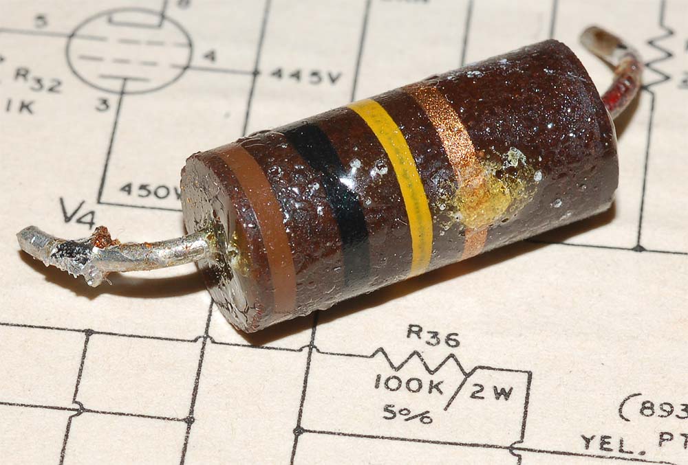
The solution to this is to check the resistance of the resistor that feeds the bias supply circuit. The schematic in my 1972 B15N names it R36, 100K 2W. It is supposed to have a 100K ohms value but is very likely to be significantly different if this resistor has not been changed.
1968 B-15N schematic
Click image for larger size |
871 Revision A - August 1971 B-15N schematic Ultra Hi / Ultra Lo switches 
Click image for larger size |
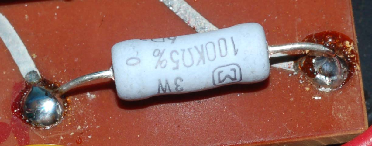
The common resistor technology available at the time these amps were in production was a carbon composition material which has long since been superceded by metal oxide film resistor (MOF) technology.
Original 1972 part
Click image for larger size
Fear not - a 50 cent MOF resistor cures all. The part of choice is a
Matsushita, 100K-ohm, 3W, 500V max. These resistors are stable, accurate
and reliable. Even during high current loads they stay well within
tolerance - perfectly suited for the job. I got mine from a fellow ham
radio operator, Rich AG6K.
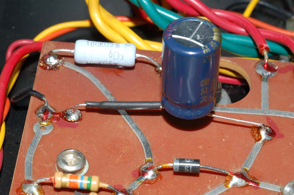
Below is a photo of the new resistor installed on the circuit board:
Click image for larger size
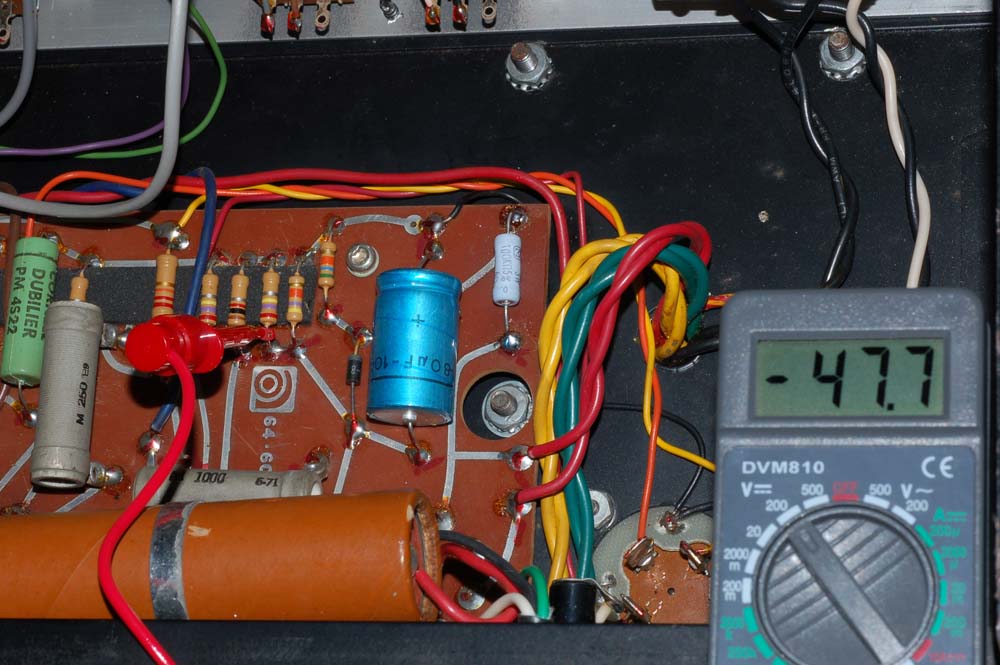
The net result of changing this one resistor is the bias voltage is
approximately -48V in operation and nearly -80V during standby. In
standby mode the tube is biased to cut-off and no plate current, nearly
0mA.
Click image for larger size
You're not finished, yet. Don't forget the bias supply filter capacitor.
Click image for larger size
Save yourself from future hassle and replace the bias supply's aluminum
electrolytic capacitor. Be sure to put some shrink wrap tubing around the
leg which crosses the bias supply board trace - bad things could result if you don't.
Ampeg appears to have used the Amperex brand for this part. New-old-stock (NOS) Amperex Holland capacitors like this one can still be had for $15 but they're as old as the one you're replacing and definitely will have different performance characteristics. NOS capacitors that sit unused, presumably in climate controlled conditions, for 35 years will behave differently than those that have been less than an inch away from a serious heat generator so you're not going to buy "original tone" by acquiring NOS for this specific capacitor.
Some amps (like mine) shipped with 80uF/100V, others with 100uF/100V (the schematic calls for 100uF/100V). The time constant (how quickly the capacitor charges when idle and discharges when under load) between 80uF and 100uF is nearly the same and tolerances will vary within production runs. I need to verify this but I have not noticed that the bias voltage changes more than 0.5V between silence and full tilt output.
My recommendations are the Panasonic ECG EEUFC2A101 or Sprague / Vishay 2222 118 19101, group 118 AHT. Both of these capacitor models are chosen for long life (5,000+ hours) and operation in high heat environments - there's no air circulation inside the amp chassis and this capacitor is in close proximity to the bias supply resistor. Either one will work fine.
All totalled, the time required to replace these two parts is about 15 minutes and the cost is under $5.
I used the AMP-HEAD Bias Tester to measure the plate current for each 6L6 tube - this is a fine product, no one should be without it. Match your own tubes, and find out if the "matched" pair you paid a high price for are really matched, or not.
Matched pairs of tubes with extremely high transconductance, or gain, may require adjustment of the bias voltage to -55V or -60V to reduce the idle plate current to reasonable values. I compared two genuinely unused new old stock 6L6GC tubes from the same manufacturer and one had very high gain and ran at nearly 70mA when idle - this is way too high. The "Amp Head" bias tester is a must-have - I would not have known this was happening without the tester and it's a lot cheaper than buying a Hickok tube tester.
Line voltage plays a significant role in the bias voltage presented to the tube grids and to the plates (anode). If you use a variac to adjust the voltage feeding the amplifier (ala Van Halen Brown Sound you will notice that 110VAC yields approximately 450VDC to the plates, where 120VAC is closer to 510VAC. The bias voltage will change a bit as well, at -45V at 110VAC, and -52V at 120VAC. The sweet-spot to maintain -50V in the original Ampeg B-15 design requires 117VAC line voltage, although this will vary from amp to amp as components age. Note that in the 6L6GC tube specification data sheets the distortion products are lower at 450V than at 500V.
A word of caution about under-biasing the tubes - if you apply -40V to the grids the plate current increases well over 50mA per tube, distortion increases and creates richer harmonics but this is at the expense of the health of the power transformer. Heat kills transformers - 70mA per tube in the B-15 will cause the power transformer to get very warm just sitting idle (not in standby).
36mA (25W @ 70%)
42mA (30W @ 70%)
26mA (25W @ 50%)
31mA (30W @ 50%)
If the current draw is within 5mA for each tube the output will be optimum, but check the power transformer heat. If it's warm the tubes may be drawing too much current.
Assuming 117VAC line mains, -50V grid bias, 480VDC anode voltage running each tube at a conservative 25W dissipation equates to approximately 36mA per tube - at rated 30W dissipation 42mA is the limit. It'll last forever. If that isn't loud enough you'd probably be better served getting an Ampeg SVT amp - they're in production and made to give you the big sound you're looking for. You'll have to let your ear be the judge, but the scarcity of good quality 6L6GC tubes and B-15 amps, to me, makes it worthwhile not to abuse the amp.
Ampeg never emphasized measurements of the actual plate current - bias voltage was their concern - I contacted Jess Oliver about plate current, bias voltage, etc. for 6L6GCs. His advice was to maintain -50V bias and mentioned that some later schematics call for -55V which would further reduce plate current.
Not exactly for the faint of heart but the hum balance rheostat can benefit
by a little drop of CAIG Deoxit (literally, a single drop, two at most) on the
winding and wiper.
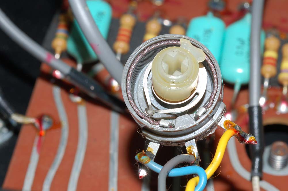
Click image for larger size
To get at the insides you will need a 1/2" nut driver to remove the nut from
the outside of the chassis, then some very narrow needle-nose pliers and
thin flat-blade screwdriver to very carefully bend back the metal
tabs that hold the metal shell against the body of the rheostat. The
insides are easily dealt with, but the entire assembly will come apart. Put
a small amount of Deoxit near the 10:00 and 2:00 location on the windings. Do
this with lots of light and patience. Rotate the wiper a few times to
ensure that the Deoxit fluid flows evenly across the metal windings.
Deoxit's cleaning properties are preferable for this application over ProGold -
use sparingly. Quickly wipe up any spills on the (brown) phenolic circuit board.
The hum balance control will be good to go for
another 35 years. The metal tabs that hold the assembly together aren't
made to be bent more than 2 or 3 times...